9 Hands-On GLSL Examples for Shader Newbies
Last updated on 15 Dec, 2024 | ~19 min read
Learning the basics of GLSL is a piece of cake. However, applying that knowledge to create effects can be intimidating, as you might feel lost and unsure where to begin. If that sounds familiar, then this tutorial is just for you.
If you need to brush up on the basics, check out this article; it will provide you with all the necessary knowledge to follow this tutorial.
Resolution, Mouse, and Time
In the first examples, we'll be using the Book of Shader's Editor. So, open it up and let's get started with our first example.
First, let's discuss u_resolution, a vec2 uniform that contains the canvas's width and height in pixels.
As you know, GLSL operates within a coordinate system that ranges from 0 to 1, so we need to normalize our values accordingly.
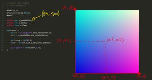
To achieve this, we divide the coordinates of the current fragment (gl_FragCoord) by the resolution (u_resolution).
vec2 st = gl_FragCoord.xy / u_resolution.xy;This results in a horizontal gradient, where 0 represents black and 1 represents white.
#ifdef GL_ES
precision mediump float;
#endif

uniform vec2 u_resolution;

void main() {
  vec2 st = gl_FragCoord.xy / u_resolution.xy;

  vec3 color = vec3(st.x);

  gl_FragColor = vec4(color, 1.);
}
Replace st.x with st.y to create a vertical gradient.
vec3 color = vec3(st.y);To invert the colors, simply subtract the value from 1.
vec3 color = vec3(1. - st.y);The next uniform is the cursor's coordinates (u_mouse), which are also expressed in pixels. We normalize these by dividing them by the resolution as well.
vec2 mousePos = u_mouse.xy / u_resolution.xy;This allows us to use the x-coordinate of the mouse position to adjust the gradient.
#ifdef GL_ES
precision mediump float;
#endif

uniform vec2 u_resolution;
uniform vec2 u_mouse;

void main() {
  vec2 st = gl_FragCoord.xy / u_resolution.xy;
  vec2 mousePos = u_mouse.xy / u_resolution.xy;

  vec3 color = vec3(mousePos.x);

  gl_FragColor = vec4(color, 1.);
}
Now let's make things a bit more interesting. We'll create a fading circle that surrounds the cursor.
To achieve this, we'll set the fragment's color based on its distance from the mouse position. The closer the distance, the darker the fragment will be, with values approaching 0 (black).
To calculate the distance, we'll use the predefined distance() function.
#ifdef GL_ES
precision mediump float;
#endif

uniform vec2 u_resolution;
uniform vec2 u_mouse;
uniform float u_time;

void main() {
  vec2 st = gl_FragCoord.xy/u_resolution.xy;
  vec2 mousePos = u_mouse.xy / u_resolution.xy;

  float d = distance(st, mousePos);

  vec3 color = vec3(d);

  gl_FragColor = vec4(color, 1.);
}
To invert the colors, we'll subtract the calculated value from 1.
float d = 1. - distance(st, mousePos);To control the circle's radius, we'll use the pow() function. Increasing the exponent will decrease the circle's size.
vec3 color = vec3(pow(d, 10.));The third uniform is a float that represents the time (surprisingly!). It's the number of seconds since the shader started running.
So, let's incorporate it into our code by multiplying it with the exponent.
#ifdef GL_ES
precision mediump float;
#endif

uniform vec2 u_resolution;
uniform vec2 u_mouse;
uniform float u_time;

void main() {
  vec2 st = gl_FragCoord.xy/u_resolution.xy;
  vec2 mousePos = u_mouse.xy / u_resolution.xy;

  float d = 1. - distance(st, mousePos);

  vec3 color = vec3(pow(d, 10. * u_time));

  gl_FragColor = vec4(color, 1.);
}
This causes the circle to disappear because the exponent becomes large. As you know, increasing the exponent of a fractional number results in smaller values. Consequently, the color value approaches 0.
Next we'll apply the sin() function to the time, which returns values between -1 and 1, making the circle animated.
vec3 color = vec3(pow(d, 10. * sin(u_time)));Notice that the canvas remains white for longer periods when the sin() returns negative values.
To balance the animation, we'll use the abs() function to consider only positive values.
vec3 color = vec3(pow(d, 10. * abs(sin(u_time))));The final step involves reducing the circle's radius to maintain the gradient when sin() returns 1.
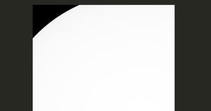
vec3 color = vec3(pow(d, 10. * abs(1.2 - sin(u_time))));Circle and Torus
The primary focus here is to avoid value interpolation, which leads to the creation of the gradient.
If, for example, I want a defined black circle, I need the values within its radius to be exactly 0, with the rest set to 1, avoiding any in-between values.
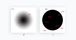
To achieve this, we can use the GLSL built-in function step(). This function compares its two inputs: if the second argument is less than the first, it returns 0; if it's greater, it returns 1
#ifdef GL_ES
precision mediump float;
#endif

uniform vec2 u_resolution;

void main() {
  vec2 st = gl_FragCoord.xy/u_resolution.xy;

  float d1 = step(0.5, distance(vec2(0.5), st));

  vec3 color = vec3(d1);

  gl_FragColor = vec4(color, 1.);
}
With this line of code, I'm essentially stating that if the distance of the current fragment to the center is less than 0.5, make it black; otherwise, set it to white.
float d1 = step(0.5, distance(vec2(0.5), st));The 0.5 used as the first argument represents the circle's radius, allowing you to adjust its size.
Now, to draw a torus, I'll create another circle and combine it with the existing one. However, this new circle needs to be white, so I'll invert its color by subtracting it from 1.
Note: After these examples, you've probably noticed that your mind directly associates subtracting from 1 with color inversion. This is how you start linking mathematical equations and functions to the effects you want to achieve.
float d1 = step(0.44, distance(vec2(0.5), st));
float d2 = step(0.6, 1. - distance(vec2(0.5), st));
vec3 color = vec3(d1 + d2);
Now, the argument of step() used to calculate d1 represents the outer radius, while the first argument of step() used to calculate d2 represents the inner radius of the torus.
Pulsating Light
In GLSL, the built-in function fract() returns the decimal part of a floating-point number.
So, when I apply fract() here, you can see that we obtain almost the same, if not exactly the same, gradient as when using st.x.
#ifdef GL_ES
precision mediump float;
#endif

uniform vec2 u_resolution;

void main() {
  vec2 st = gl_FragCoord.xy/u_resolution.xy;

  vec3 color = vec3(fract(st.x));

  gl_FragColor = vec4(color, 1.);
}
Now, multiply the argument by 10., and you'll get a repeated gradient pattern.
vec3 color = vec3(fract(10. * st.x));Now, to transform this into a radial pattern, replace st.x with the distance from the center.
float d = distance(vec2(0.5), st);

vec3 color = vec3(fract(10. * d));
To animate it, subtract u_time.
Note: whenever we talk about animation, you should immediately think of incorporating time—it's a rule of thumb.
#ifdef GL_ES
precision mediump float;
#endif

uniform vec2 u_resolution;
uniform float u_time;

void main() {
  vec2 st = gl_FragCoord.xy/u_resolution.xy;

  float d = distance(vec2(0.5), st);

  vec3 color = vec3(fract(10. * d - u_time));

  gl_FragColor = vec4(color, 1.);
}
Furthermore, divide everything by the distance, and then divide it again by 40.
vec3 color = vec3(fract(10. * d - u_time)) / d / 40.;Finally, let's introduce some color. To do this, create a vec3 variable containing arbitrary values. Then, you can experiment with various operators to achieve different and visually appealing effects.
#ifdef GL_ES
precision mediump float;
#endif

uniform vec2 u_resolution;
uniform float u_time;

void main() {
  vec2 st = gl_FragCoord.xy/u_resolution.xy;

  float d = distance(vec2(0.5), st);

  vec3 color = vec3(fract(10. * d - u_time)) / d / 40.;

  vec3 color2 = vec3(0.1, 0.5, 0.9);

  // Try /, +, and *
  gl_FragColor = vec4(color - color2, 1.);
}
Chess Pattern
The floor() function rounds a floating-point number down to the nearest integer that is less than or equal to the original number.
Examples:
floor(0.7) === 0.
floor(2.2) === 2.
floor(3.9) === 3.
On the other hand, mod() calculates the remainder of a division operation between two numbers.
Examples:
mod(6., 2.) === 0.
mod(5., 2.) === 1.
mod(10., 4.) === 2.
Now, when we apply the floor() function to st.x, we still get the same black canvas.
#ifdef GL_ES
precision mediump float;
#endif

uniform vec2 u_resolution;

void main() {
  vec2 st = gl_FragCoord.xy/u_resolution.xy;

  float checkerX = floor(st.x);

  vec3 checker = vec3(checkerX);

  gl_FragColor = vec4(checker, 1.);
}
To make a noticeable change, multiply the input by an arbitrary number.
#ifdef GL_ES
precision mediump float;
#endif

uniform vec2 u_resolution;

void main() {
  vec2 st = gl_FragCoord.xy/u_resolution.xy;

  float frequency = 5.;

  float checkerX = floor(st.x * frequency);

  vec3 checker = vec3(checkerX);

  gl_FragColor = vec4(checker, 1.);
}
With that done, apply the mod() function to the result to create a pattern.
vec3 checker = vec3(mod(checkerX, 2.0));Next, duplicate the flooring line but use st.y instead of st.x to create horizontal lines. Then, add these to mod() to form a checkerboard pattern.
float checkerX = floor(st.x * frequency);

float checkerY = floor(st.y * frequency);

vec3 checker = vec3(mod(checkerX + checkerY, 2.));
Now, we can animate this by incorporating the u_time variable.
#ifdef GL_ES
precision mediump float;
#endif

uniform vec2 u_resolution;
uniform float u_time;

void main() {
  vec2 st = gl_FragCoord.xy/u_resolution.xy;

  float frequency = 5.;

  float checkerX = floor(st.x * frequency + u_time);

  float checkerY = floor(st.y * frequency);

  vec3 checker = vec3(mod(checkerX + checkerY, 2.));

  gl_FragColor = vec4(checker, 1.);
}
To control the speed, we'll need to multiply u_time by another float.
float speed = 2.;

float checkerX = floor(st.x * frequency + u_time * speed);
Rotate and Scale
To rotate whatever we have, we need to use a rotation matrix.
So, I'll create a function that takes the rotation angle as an argument and returns a rotation matrix.
mat2 rotate(float angle) {
  return mat2(cos(angle), -sin(angle), sin(angle), cos(angle));
}
Now, when we apply this to the canvas, you'll notice that the rotation origin is at the (0, 0) point.
#ifdef GL_ES
precision mediump float;
#endif

uniform vec2 u_resolution;
uniform float u_time;

mat2 rotate(float angle) {
    return mat2(cos(angle), -sin(angle), sin(angle), cos(angle));
}

void main() {
  vec2 st = gl_FragCoord.xy/u_resolution.xy;

  st *= rotate(sin(u_time * 0.1) * 5.);

  float frequency = 5.;

  float checkerX = floor(st.x * frequency);

  float checkerY = floor(st.y * frequency);

  vec3 checker = vec3(mod(checkerX + checkerY, 2.));

  vec3 color = vec3(0.423, 0.435, 0.800);

  gl_FragColor = vec4(checker + color, 1.);
}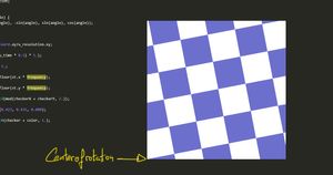
To make the center of the canvas the rotation origin, adjust the coordinate system by shifting it by half before applying the rotation, and then shift it back afterward.
st -= vec2(0.5);
st *= rotate(sin(u_time * 0.1) * 5.);
st += vec2(0.5);
The same principle applies when scaling objects; we just need to use a different matrix for scaling.
#ifdef GL_ES
precision mediump float;
#endif

uniform vec2 u_resolution;
uniform float u_time;

mat2 rotate(float angle) {
    return mat2(cos(angle), -sin(angle), sin(angle), cos(angle));
}

mat2 scale(vec2 scale) {
    return mat2(scale.x, 0., 0., scale.y);
}

void main() {
  vec2 st = gl_FragCoord.xy/u_resolution.xy;

  st -= vec2(0.5);
  st *= rotate(sin(u_time * 0.1) * 5.);
  st += vec2(0.5);

  st -= vec2(0.5);
  st *= scale(vec2(sin(u_time * 0.1) * 8.));
  st += vec2(0.5);

  float frequency = 5.;

  float checkerX = floor(st.x * frequency);

  float checkerY = floor(st.y * frequency);

  vec3 checker = vec3(mod(checkerX + checkerY, 2.));

  vec3 color = vec3(0.423, 0.435, 0.800);

  gl_FragColor = vec4(checker + color, 1.);
}
Integrating the Shader into a Three.js Application
The square in the Book of Shader's Editor represents the entire scene. However, in real-life examples, you may want to apply the same effect to a plane within the scene, rather than to the entire scene itself.
That said, let's apply the same effect we used in the first example to a plane in a Three.js application.
First, create a Three.js application or use my Three.js boilerplate.
Next, copy and paste the following code into your main.js and index.html files.
main.js:
import * as THREE from 'three';
import { OrbitControls } from 'three/examples/jsm/controls/OrbitControls.js';

const renderer = new THREE.WebGLRenderer({ antialias: true });
renderer.setSize(window.innerWidth, window.innerHeight);
document.body.appendChild(renderer.domElement);

const scene = new THREE.Scene();
const camera = new THREE.PerspectiveCamera(
  45,
  window.innerWidth / window.innerHeight,
  0.1,
  1000
);

// Sets orbit control to move the camera around
const orbit = new OrbitControls(camera, renderer.domElement);

// Camera positioning
camera.position.set(6, 8, 14);
orbit.update();

const uniforms = {
  u_time: { value: 0.0 },
  u_resolution: {
    value: new THREE.Vector2(
      window.innerWidth,
      window.innerHeight
    ).multiplyScalar(window.devicePixelRatio),
  },
  u_mouse: { value: new THREE.Vector2(0.0, 0.0) },
};

window.addEventListener('mousemove', function (e) {
  uniforms.u_mouse.value.set(
    e.offsetX / this.window.innerWidth,
    1 - eoffsetnY / this.window.innerHeight
  );
});

const geometry = new THREE.PlaneGeometry(10, 10, 30, 30);
const customMaterial = new THREE.ShaderMaterial({
  vertexShader: document.getElementById('vertexshader').textContent,
  fragmentShader: document.getElementById('fragmentshader').textContent,
  uniforms,
});
const mesh = new THREE.Mesh(geometry, customMaterial);
scene.add(mesh);

const clock = new THREE.Clock();
function animate() {
  uniforms.u_time.value = clock.getElapsedTime();
  renderer.render(scene, camera);
}

renderer.setAnimationLoop(animate);

window.addEventListener('resize', function () {
  camera.aspect = window.innerWidth / window.innerHeight;
  camera.updateProjectionMatrix();
  renderer.setSize(window.innerWidth, window.innerHeight);
});index.html:
<!DOCTYPE html>
<html lang="en">
  <head>
    <meta charset="UTF-8" />
    <meta http-equiv="X-UA-Compatible" content="IE=edge" />
    <meta name="viewport" content="width=device-width, initial-scale=1.0" />
    <title>Wael Yasmina Three.js boilerplate</title>
    <style>
      body {
        margin: 0;
      }
    </style>
  </head>
  <body>
    <script id="vertexshader" type="vertex">
      void main() {
          gl_Position = projectionMatrix * modelViewMatrix * vec4(position, 1.0);
      }
    </script>

    <script id="fragmentshader" type="fragment">
      uniform float u_time;
      uniform vec2 u_resolution;
      uniform vec2 u_mouse;
      void main() {
          gl_FragColor = vec4(1.0);
      }
    </script>
    <script src="/main.js" type="module"></script>
  </body>
</html>
I've explained everything in these two snippets in the examples section of this article: GLSL and Shaders Tutorial for Beginners (WebGL / Threejs). So if something is confusing, check out the article for clarification.
Now, copy and paste the shader from the first example into the fragment shader of your application.
Note: in the new code, I removed the normalization of the mouse position coordinates from the fragment shader because it is already handled in the JavaScript code.
<script id="fragmentshader" type="fragment">
uniform float u_time;
uniform vec2 u_resolution;
uniform vec2 u_mouse;
void main() {
  vec2 st = gl_FragCoord.xy/u_resolution.xy;

  float d = 1. - distance(st, u_mouse);

  vec3 color = vec3(pow(d, 10. * abs(sin(u_time))));

  gl_FragColor = vec4(color, 1.);
}
</script>
Now, you should see the same animation but with a large offset. This is because the effect is applied based on the size of the entire scene rather than just the plane.
To fix this, first multiply the x-coordinate of the mouse position by the aspect ratio of the window.
window.addEventListener('mousemove', function (e) {
  const vpRatio = this.window.innerWidth / this.window.innerHeight;

  uniforms.u_mouse.value.set(
    (e.offsetX / this.window.innerWidth) * vpRatio,

    1 - e.offsetY / this.window.innerHeight
  );
});
Next, in the fragment shader, multiply the x-coordinate of the canvas by its aspect ratio.
uniform float u_time;
uniform vec2 u_resolution;
uniform vec2 u_mouse;
void main() {
  vec2 st = gl_FragCoord.xy/u_resolution.xy;

  st.x *= u_resolution.x / u_resolution.y;

  float d = 1. - distance(st, u_mouse);

  vec3 color = vec3(pow(d, 10. * abs(sin(u_time))));

  gl_FragColor = vec4(color, 1.);
}Texture
In this example, we'll see how to map a texture onto a cylinder.
First and foremost, place an image in the public folder of your project directory.
Next, in the main.js file, load the texture and pass it to the uniforms object. Then, comment out the plane code and create a cylinder instead.
const uniforms = {
  u_texture: { value: new THREE.TextureLoader().load('/fries.jpg') },
};
//const geometry = new THREE.PlaneGeometry(10, 10, 30, 30);
const geometry = new THREE.CylinderGeometry(2, 2, 0, 100);
const customMaterial = new THREE.ShaderMaterial({
vertexShader: document.getElementById('vertexshader').textContent,
fragmentShader: document.getElementById('fragmentshader').textContent,
uniforms,
});
const mesh = new THREE.Mesh(geometry, customMaterial);
scene.add(mesh);Now, we'll use the texture2D() function, which takes two arguments: the image and the texture coordinates.
This function's purpose is to retrieve the color information, also known as texels, from an a texture and then sample that 2D texture at a specified texture coordinate.
You can observe that the cylinder now displays a portion of the texture, creating a cool effect. However, if you'd like the texture to fit the surface of the object, you need to pass the texture coordinates of the cylinder to the texture2D() function instead of the coordinates of the entire scene.
To achieve that, we need to create a varying variable to transfer the texture coordinates of the mesh from the vertex shader to the fragment shader. Then, assign the value of the predefined uv variable to it.
<script id="vertexshader" type="vertex">
  varying vec2 vUv;
  void main() {
    vUv = uv;
    gl_Position = projectionMatrix * modelViewMatrix * vec4(position, 1.0);
  }
</script><script id="fragmentshader" type="fragment">
varying vec2 vUv;
uniform sampler2D u_texture;
void main() {
vec4 texel = texture2D(u_texture, vUv);
gl_FragColor = texel;
}
</script>Radar Signal
Images are not only used for direct mapping onto meshes but can also be employed to create impressive effects and animations.
To start, I'll demonstrate how to create a radar-like effect using this image.
First, I'll choose an arbitrary color and use the texture's texels for the alpha channel. Also, don't forget to load the texture and associate it with a sampler2D variable.
varying vec2 vUv;

uniform sampler2D u_texture;
void main() {

  // u_texture is the black and white image
  vec4 texel = texture2D(u_texture, vUv);

  gl_FragColor = vec4(vec3(0.4, 0.5, 1.0), texel.r);
}
As you can see, we get a radial bluish gradient, but the transparency isn't working.
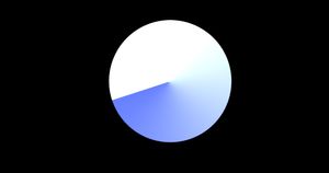
To fix that, set the transparent property of the material to true.
We can't have a radar signal effect without animation. So, I'll use the rotation technique we learned earlier to rotate the cylinder's texture coordinates.
varying vec2 vUv;

uniform float u_time;

uniform sampler2D u_texture;

mat2 rotate(float angle) {
  return mat2(cos(angle), -sin(angle), sin(angle), cos(angle));
}
void main() {

  vec2 vUv = vUv;

  vUv -= vec2(0.5);
  vUv *= rotate(sin(u_time * 0.1) * 5.);
  vUv += vec2(0.5);

  // u_texture is the black and white image
  vec4 texel = texture2D(u_texture, vUv);

  gl_FragColor = vec4(vec3(0.4, 0.5, 1.0), texel.r);
}
Note that I created another vUv variable, which we modified with rotation, as we are not allowed to alter the values of varying variables.
Another interesting thing we can do is layer this effect on top of another texture.
To achieve that, I'll pass the RGB values from the texture first.
varying vec2 vUv;

uniform float u_time;

uniform sampler2D u_texture;
uniform sampler2D u_texture2;

mat2 rotate(float angle) {
  return mat2(cos(angle), -sin(angle), sin(angle), cos(angle));
}
void main() {

  vec2 vUv = vUv;

  vUv -= vec2(0.5);
  vUv *= rotate(sin(u_time * 0.1) * 5.);
  vUv += vec2(0.5);

  // u_texture is the black and white image
  vec4 texel = texture2D(u_texture, vUv);

  // The cupcake image
  vec4 texel2 = texture2D(u_texture2, vUv);

  gl_FragColor = vec4(texel2.rgb, texel.r);
}
To prevent the second texture from rotating, I'll create a variable to hold the original UV coordinates before the rotation and pass those to the texture2D() function.
varying vec2 vUv;

uniform float u_time;

uniform sampler2D u_texture;
uniform sampler2D u_texture2;

mat2 rotate(float angle) {
  return mat2(cos(angle), -sin(angle), sin(angle), cos(angle));
}
void main() {

  vec2 vUv = vUv;
  vec2 vUv2 = vUv;

  vUv -= vec2(0.5);
  vUv *= rotate(sin(u_time * 0.1) * 5.);
  vUv += vec2(0.5);

  // u_texture is the black and white image
  vec4 texel = texture2D(u_texture, vUv);

  // The cupcake image
  vec4 texel2 = texture2D(u_texture2, vUv2);

  gl_FragColor = vec4(texel2.rgb, texel.r);
}Fade
The clamp() function takes three inputs: a value, and a range defined by a minimum and maximum value. If the first input falls within the range, the function returns the same value. If it's lower than the minimum, the function returns the minimum value of the range. Conversely, if it's greater than the maximum, it returns the maximum value of the range.
The mix() function performs linear interpolation, also known as lerp, between two values. In simple terms, it returns values that transition between these two values.
With that said, we'll use these two functions to create a smooth transition effect between two textures on a mesh.
First and foremost, have two images ready to transition between. Also the black and white radar texture we used earlier and this new one.
Now, create a new float property named mixRatio in the uniforms object. This variable will control the amount of transition effect.
Next, stop the server temporarily and install lil-gui so we can control the value of that variable through an interface. To do this, run the command npm install lil-gui in your terminal.
Import the library, create the params object, and link the value of mixRatio property in the params object to the mixRatio in the uniforms object.
By the way, I'm assuming you're familiar with what the lil-gui library is and how it works. If not, check out the section dedicated to it in my Three.js tutorial.
import { GUI } from 'lil-gui';const gui = new GUI();
const params = {
mixRatio: 0.0,
};
gui.add(params, 'mixRatio', 0.0, 1.0).onChange(function (value) {
uniforms.mixRatio.value = value;
});
const uniforms = {
u_texture: { value: new THREE.TextureLoader().load('/burger1.jpg') },
u_texture2: { value: new THREE.TextureLoader().load('/burger2.jpg') },
u_transition: { value: new THREE.TextureLoader().load('/transition.png') },
u_transition2: { value: new THREE.TextureLoader().load('/transition2.png') },
mixRatio: { value: 0.0 },
};And here is the fragment shader.
varying vec2 vUv;

uniform float u_time;

uniform sampler2D u_texture;
uniform sampler2D u_texture2;

uniform sampler2D u_transition;
uniform sampler2D u_transition2;

uniform float mixRatio;

void main() {

  vec2 vUv = vUv;

  // burger 1 image
  vec4 texel = texture2D(u_texture, vUv);

  // Burger2 image
  vec4 texel2 = texture2D(u_texture2, vUv);

  gl_FragColor = mix(texel, texel2, mixRatio);
}
First, let's observe what a basic call to the mix() function on two textures does by adjusting the mixRatio value.
By doing this, you'll see that when the mixRatio is 0, only the first texture is visible. When it's 1, only the second texture is visible. Values in between create a blend of the two textures.
Now, we'll use another texture to shape the transition effect. To do this, we'll employ some math, including the clamp() function we discussed earlier, to control the value of the mix.
varying vec2 vUv;

uniform sampler2D u_texture;
uniform sampler2D u_texture2;

uniform sampler2D u_transition;
uniform sampler2D u_transition2;

uniform float mixRatio;

void main() {

  vec2 vUv = vUv;

  // burger 1 image
  vec4 texel = texture2D(u_texture, vUv);

  // Burger 2 image
  vec4 texel2 = texture2D(u_texture2, vUv);

  // transition texture 1
  vec4 transitionTexel = texture2D(u_transition, vUv);

  // transition texture 2
  vec4 transitionTexel2 = texture2D(u_transition2, vUv);

  float r = mixRatio * 1.6 - 0.3;

  // Try transitionTexel2 for another effect
  float mixF = clamp((transitionTexel.r - r) * 3.33, 0.0, 1.0);

  gl_FragColor = mix(texel, texel2, mixF);
}Wrap Up
This article may end here, but your creative journey is just beginning! I hope this post provided you with the insights and, most importantly, the motivation to conquer your fears and start honing your shader creation skills. Remember, practice makes perfect!
Until next time!
